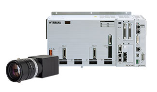
Multi-axis controller RCX340
Introduces the multi-axis controllers, RCX340.
Specification
| Basic specifications | ||||
|---|---|---|---|---|
| Applicable robots | YAMAHA single-axis robots, linear single-axis robots, Cartesian robots, SCARA robots (except for YK120X and YK150X), P&P robots | |||
| Connectedmotor capacity | 1600W or less (in total for 4 axes) | |||
| Power capacity | 2500VA | |||
| Dimensions | W355 × H195 × D130mm (main unit only) | |||
| Weight | 6.2kg (main unit only) | |||
| Input power supply | Control power supply | Single-phase 200 to 230V AC +/-10% maximum, 50/60Hz | ||
| Main power supply | Single-phase 200 to 230V AC +/-10% maximum, 50/60Hz | |||
| Axis control | ||||
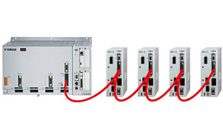
| No. of controllable axes | Max. 4 axes (simultaneous control: 6 axes) Expandable to up to 16 axes (4 robots) using YC-Link/E. |
|||
| Drive method | AC full digital servo | |||
| Position detection method | Resolver or magnetic linear scale | |||
| Control method | PTP motion (point to point), ARCH motion, linear interpolation, circular interpolation | |||
| Coordinate systems | Joint coordinates, Cartesian coordinates | |||
| Position display units | Pulses, mm (1/1000 steps), degree (1/1000 steps) | |||
| Speed setting | 0.01 to 100% (below 1% can be changed by programming) | |||
| Acceleration/deceleration setting | Automatic acceleration setting by robot model and tip weight parameter Setting by acceleration coefficient and deceleration rate parameters (1% steps) * Can be changed by programming. Zone control (Only the SCARA robot can set an optimum speed corresponding to the arm position.) |
|||
| Programming | ||||
| Program language | YAMAHA BASIC II conforming to JIS B8439 (SLIM language) | |||
| Multi-task | Max. 16 tasks | |||
| Sequence program | 1 Program | |||
| Memory capacity | 2.1MB (Total of program and point data) (Available capacity for program when the maximum number of points is used: 300KB) |
|||
| Program | 100 programs (maximum number of programs) 9999 lines (maximum number of lines per program) |
|||
| Point | 30000 points (maximum number of points) | |||
| Point teaching method | MDI (coordinate data input), direct teaching, teaching playback, offline teaching (data input from external unit) | |||
| System backup (Internal memory backup) |
Lithium battery (service life about 4 years at 0 to 40°C) |
|||
| External I/O | ||||
| SAFETY | Input | Emergency stop ready input, 2 systems Auto mode input, 2 systems (Enabled only when the global specifications are used.) |
||
| Output | Emergency stop contact output, 2 systems Enable contact output, 2 systems (Enabled only when the PBX-E is used.) Motor power ready output, 2 systems |
|||
| Brake output | Transistor output (PNP open collector) | |||
| Origin sensor input | Connectable to 24V DC B-contact (normally closed) sensor | |||
| External communications | RS-232C : 1CH (D-SUB 9-pin (female)) Ethernet : 1CH (In conformity with IEEE802.3u/IEEE802.3) 100Mbps/10Mbps (100BASE-TX/10BASE-T) Applicable to Auto Negotiation USB : 1CH (B type) RS-422 : 1CH (Dedicated to PBX) |
|||
| General specifications | ||||
| Operating temperature | 0°C to 40°C | |||
| Storage temperature | -10°C to 65°C | |||
| Operating humidity | 35 to 85% RH (no condensation) | |||
| Noise immunity | Conforms to IEC61000-4-4 Level 3 | |||
| Protective structure | IP20 | |||
| Appliance classes | Class I | |||
| Options | ||||
| Option board Note | Parallel I/O board | Standard specifications | Dedicated input 8 points, dedicated output 9 points General-purpose input 16 points, general-purpose output 8 points NPN/PNP specifications are selected. (maximum 1 board) |
|
| Expansion specifications | General-purpose input 24 points, general-purpose output 16 points NPN/PNP specifications are selected. (maximum 4 boards) |
|||
| CC-Link board Ver1.1/2.0 | Remote I/O Dedicated input/output: 16 points each General-purpose input/output: 96 points each Remote register Input/output: 16 words each |
|||
| DeviceNet™ board | ||||
| EtherNet/IP™ board | ||||
| PROFIBUS board | ||||
| PROFINET board | ||||
| YC-Link/E board(master/slave) | Communication cycle: 1 ms, control cycle: minimum 1 ms / maximum 8 ms, maximum number of robot units: four units Maximum number of control axes: total 16 axes (including four master controller axes), maximum 12 axes for slaves only |
|||
| YRG(gripper) board | Position detection method: optical rotary encoder, minimum setting distance: 0.01 mm Speed setting: 20 to 100% relative to the maximum parameter speed, number of connected gripper units: maximum four units Drive power: DC 24V +/-10%, 1.0A Max |
|||
| Tracking board | Number of connected encoders: maximum two units, supported encoders: 26LS31/26C31 equivalent line driver (RS422 compliant) Encoder power supply: DC5V (2 counter (ch) total 500 mA or less) (supplied from controller) |
|||
| RCXiVY2+ unit | Camera pixels: maximum 5 million pixels, number of registered models: 254 models, number of connected cameras:
maximum two units Power supply: DC24V +/-10% 1.5A Max |
|||
| Programming box | PBX, PBX-E | |||
| Absolute battery | 3.6V 2750mAH / axis Backup retention time: About 1 year | |||
| Support software for personal computer | RCX-Studio 2020 | |||
- Note.
- There are four slots in which option boards can be installed.
External View
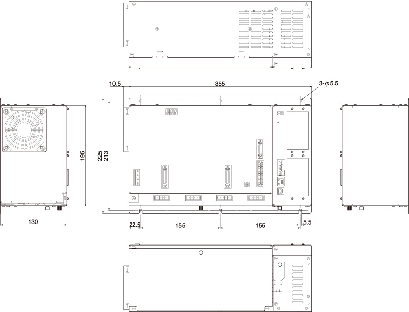
Multi-axis controller RCX340
Related contents
- Robot vision RCXiVY2+
- Yamaha's own unique solution for integrated robot vision
- Field Networks (RCX)
- Robot controller RCX series is applicable to the field networks CC-Link, DeviceNet, Profibus, Ethernet, EtherNet/IP.
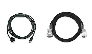
- Cable
- Dimensional diagrams and model numbers of the robot cables, cable terminals, and connectors are available.

- Basic operation of the RCX340 Controller
- This video explains the basic operations of the Yamaha robot.
Robotics Business Unit
Sales & Marketing Section
FA Sales & Marketing Division
127 Toyooka, Chūō-ku, Hamamatsu, Shizuoka 433-8103, Japan
Telephone +81-53-525-8350 /
Facsimile +81-53-525-8378