Yamaha Motor Launch New i-PULSE 3D HYBRID SURFACE MOUNTERS, New models S10 & S20 enables mounting on concave-convex, sloped and curved surfaces
May 28, 2015
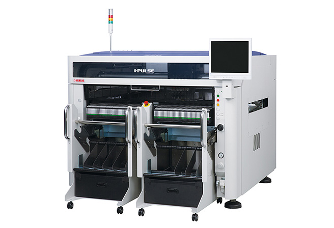
IWATA, May 28, 2015- Yamaha Motor Co., Ltd. (Tokyo: 7272) announces the release of its new S10 and S20 i-PULSE 3D HYBRID SURFACE MOUNTERS with enhanced support for MID's (Molded Interconnect Devices) from September 1, 2015.
The S10 and S20 have been developed under the concept of a single unit Manufacturing Center designed for surface mounting, dispensing and inspecting. In addition to having superior product loading speed and accuracy as well as highly versatile mounting options from ultra-small chips to large components, these models are hybrids with their mounting heads and dispensing heads intermingled allowing alternate dispensing and mounting. The S10 and S20 are more advanced models than the existing M10 and M20 offering improved flexibility, expandability and productivity.
Through a newly developed tilt mechanism unit and a long stroke on the Z axis in the S10 and S20 models, surface mounting is now possible on concave-convex, sloped and curved surfaces bringing enhanced expandability to suit production types over and above conventional flat board types. Head variation can also be set to a 6-axis 6-theta, or 12-axis 2-theta configurations. Cost performance is further enhanced through improved in placement capability. In addition, stable dispensing and inspecting is carried out thanks to the adoption of a color fiducial mark recognition camera and newly developed lighting units.
The S20 will be on display at the JISSO PROTEC2015 (17th Jisso Process Technology Exhibition) at the Tokyo Big Sight, Japan (Koto-ku, Tokyo) from June 3-5.
| Model | i-PULSE "S10" i-PULSE "S20" |
|---|---|
| Launch Date | September 01, 2015 |
| Target Sales | 100 Units (one year from release, both within Japan and internationally) |
Background to Development
The market expansion in recent years for products that incorporate control boards such as smart phones and tablet devices, electric cars, natural energy power generation, and LED lighting are becoming more highly integrated, lightweight, thinner and smaller. In addition to this, increases are also being seen in further low- cost reduction, diversity, and a wider range of applications available.
Within the production processes required for control board manufacture, in order to achieve lightweight, compactness and high performance coupled with lower costs, changes are being seen from the conventional two-dimensional placement (flat-surface) to three-dimensional placement, and three-dimensional capability is being further down-sized and adopted in the SMT (surface mounting) fields.
By launching the S10 and S20 with even higher flexibility and productivity in their hybrid capability, we can provide more flexible support for 3D MID (Molded Interconnect Device), which can lead to greater cost-cutting through a reduction in the number of components and man-hours required in assembly work, and will result in smaller and thinner products as well as meeting a wider range of user needs in mounting, as a way to create and expand our own market.
S10, S20 Features
Enhancement for 3D MID processes are achieved thanks to the newly developed cast iron frame and tilt mechanism unit
Concave-convex, sloped and curved surface mounting achieving the possibility for the manufacture of new 3D MID (Molded Interconnect Device) are now achievable thanks to a longer stroke on the Z-axis, and Yamaha's original optimal design for its newly developed cast iron frame and tilt mechanism unit. This feature surpasses the framework of conventional SMT bringing enhancement for 3D MID processes.
3D Hybrid Functions
Hybrid placement carried out alternately for dispensing and component placement processes is achieved due to the mounting head and dispensing head being combined that allows design changes to be fitted on to each axis according to production requirements. In addition, cavity board* work becomes easier with the adoption of non-contact dispensing.
*Boards that are not flat and therefore making them more difficult to work with in solder-paste applications due to their surfaces being uneven.
Additional dispensing inspection function due to the adoption of a color fiducial mark recognition camera
More stable dispensing inspection is carried out by the adoption of a color camera and a newly developed lighting unit. Solder-paste dispense > dispense dot check > and component placement processes can now all be carried out using one machine thanks to these adaptations.
Selection available from two types of unit
Two types of head units are available, the 6-axis 6-theta unit (standard type), or the 12-axis 2-theta head unit (high performance type). Improved placement capacity and higher cost effectiveness is achieved due to the newly developed cast iron frame with lighter moving parts.
Large board handling capability
A maximum capability for long board sizes of up to 1825mm x 635mm (optional) or a maximum board size of up to 1240mm x 510mm for one-time clamping is possible. For example, significantly greater productivity is achieved by adjusting to suit a 12-axis 2-theta head unit when manufacturing long size LED boards.
Wide ranging component handling capability
A wide range of components from ultra-small 0201(0.25x0.125mm) chips to larger components up to 120 x 90mm can be handled. The unit is also capable of a component height for mounting of up to 35mm, the largest in the class.
Excellent setup capability suitable for high-mix low-volume productions
The maximum feeder lane in 8mm tape conversion is 180 types (45 types x 4 units) for the S20, and 90 types (45 types x 2 units) for the S10.
The F3 (electric feeder) feeder bank changer has the newly developed CFB-45E providing an increase in the number of feeder lanes available. Thanks to compatibility with existing M10 and M20 models, efficient use of existing feeder bank changers is possible including the existing CFB-36E, the CFB-36 F1/F2 (mechanical feeders) feeder bank changers, and the CTF-36C removable type tray feeder.
It is also able to replace the CTF-36C removable type tray feeder. Furthermore the CFB-45E, CFB-36E, and the CFB-36 can be used all at the same time within a system.
Specifications
| Model name | S10 | S20 | |
|---|---|---|---|
| Board Size |
With buffer unused | Min. L50 x W30mm to Max. L980 x W510mm |
Min. L50 x W30mm to Max. L1,480 x W510mm |
| With input or output buffers used |
Min. L50 x W30mm to Max. L420 x W510mm |
— | |
| With input and output buffers used |
Min. L50 x W30mm to Max. L330 x W510mm |
Min. L50 x W30mm to Max. L540 x W510mm |
|
| With input and output buffers used | 0.4 - 5.0mm | ||
| Placement accuracy A (μ+3σ) | CHIP ± 0.040mm | ||
| Placement accuracy B (μ+3σ) | IC ± 0.025mm | ||
| Placement angle | ± 180° | ||
| Component height (Board thickness + component height) |
6-axis 6-theta head: Max. 35mm 12-axis 2-theta head: Max. 20mm |
||
| Applicable Components | 0201-120mm x 90mm, BGA, CSP,Connectors, other odd-shaped components |
||
| Component package | 8-56mm tape (F1/F2 Feeders), 8-88mm tape (F3 Electric Feeders), Stick, Tray |
||
| Component types (8mm tape conversion) |
Max. 90 types (8mm tape), 45 lanes x 2 |
Max. 180 types (8mm tape), 45 lanes x 4 |
|
| Transfer height | 900 ± 20mm | ||
| Machine Dimensions | L1,250 x D1,770 x H1,420mm |
L1,750 x D1,770 x H1,420mm |
|
| Weight | Approx. 1,200kg | Approx. 1,500kg | |