YHX Standard Profile : YHX Controller
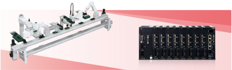
By configuring the manufacturing line itself as a robot system around YHX controller, total optimization of production facility becomes possible.
Features of YHX standard profile
- Eliminates writing ladder logic codes.
- Adding operation through a pendant.
- Perform simple direct value operation and specific point-to-point move.
- Servo ON of any slider individually.
- Obtain alarm information through the host PLC
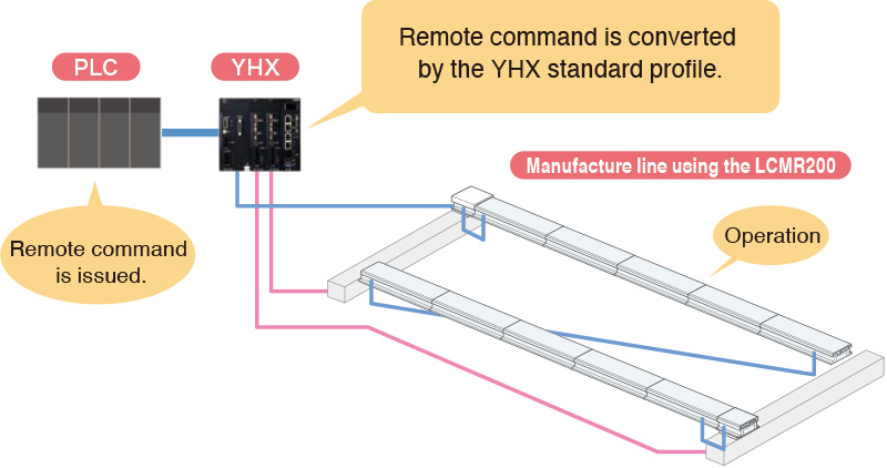
01LCMR200 can be operated using your familiar PLC.
Use of YHX standard profile makes it possible to operate the LCMR200 from the host unit such as PLC via the I/O interface of each field work.
02Creation of YHX ladder by the customer is not needed.
Dedicated input and output signals are already assigned to the word and bit area of the field network.
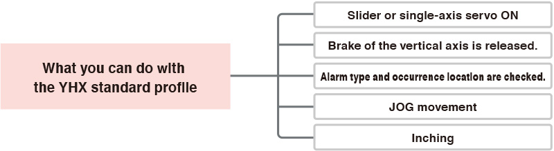
Operations necessary for the robot motion such as servo ON or JOG movement can be performed without creating programs.
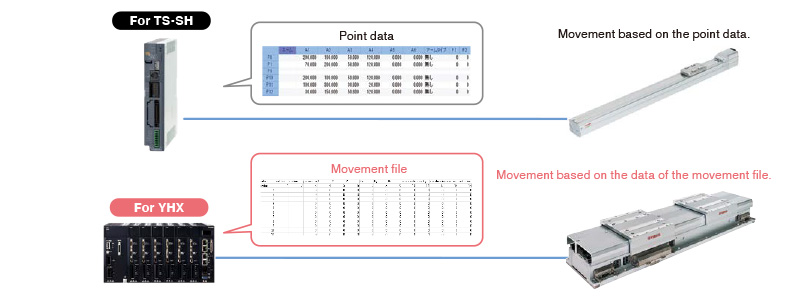
03Control using “movement file”
Control is performed using the point data “movement file” necessary to register the target position.
“Movement file” plays a role similar to point data.
04JOG or inching operation can be performed from the pendant even when no PLC is connected.
Even in a status where no PLC is connected, the axis can be operated using the JOG or inching operation from the
programming pad.
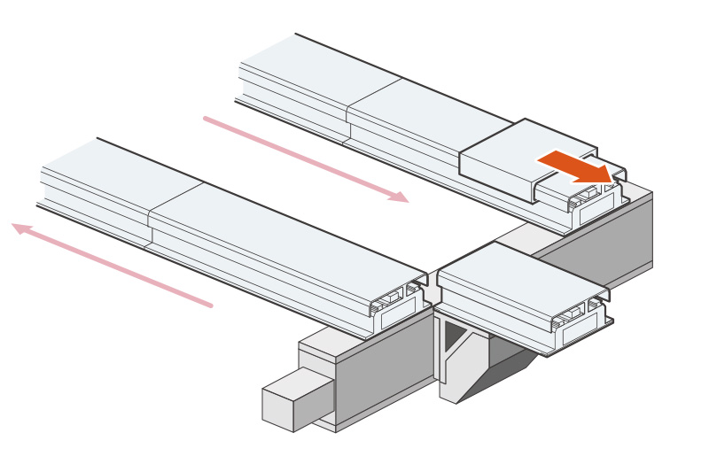
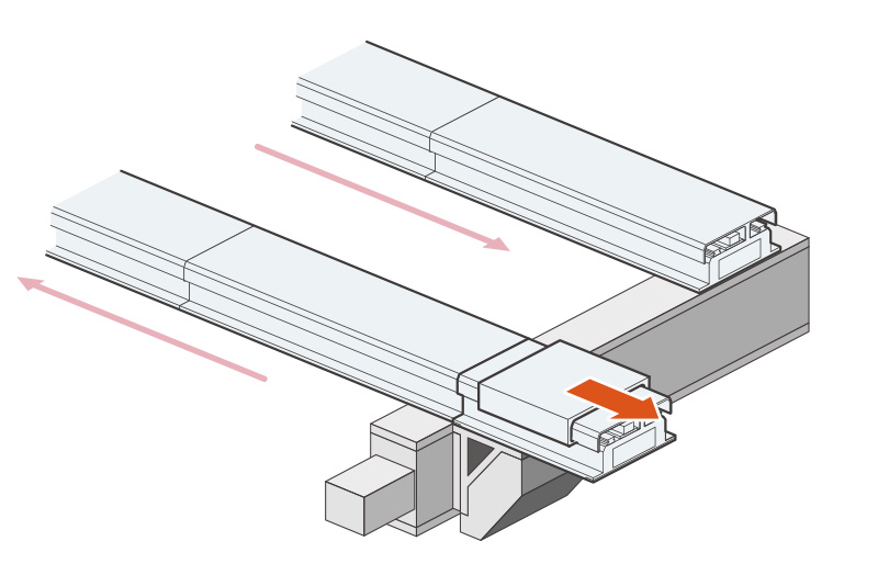
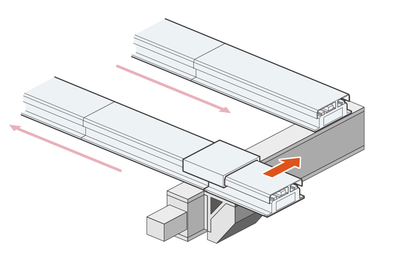
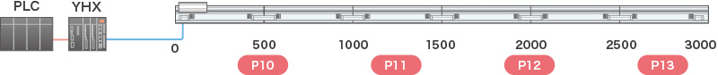
When the LCMR200 is used for the circulation layout, the necessary adjustment work can be performed immediately.
05Prevention of operation leading to damage to the circulation section is supported.
Registering the pallet size to the parameter determines the slider operable area.
Even when a pallet or workpiece is larger than the overall length of the slider, a circulation operation failure can be
detected.
This avoids any slider transfer accident of the circulation unit and allows for safer software design.
06Simple direct value operation and point designation movement can be performed.
About point designation
- The operation pattern for up to 65,535 points in total can be designated.
- The position, speed, acceleration, deceleration, and tolerance are designated for each point.
Designation image
| point | position(mm) | speed | acceleration | deceleration | tolerance(mm) |
|---|---|---|---|---|---|
| 1 | 100.000 | 1 | 0.5 | 1 | 0.01 |
| 2 | 800.000 | 0.5 | 1 | 1 | 0.05 |
| 3 | 432.562 | 1 | 1 | 1 | 0.02 |
| 4 | 1234.410 | 0.5 | 1 | 1 | 0.01 |
| 5 | 2451.400 | 1 | 1 | 1 | 0.01 |

Overview of remote command
| Input |
|---|
| 1. Command |
| 2. Point designation |
| 3. Direct value position designation |
- 1.
- Servo ON, return-to-origin, movement, JOG, inching, etc.
- 2.
- Point number to be used.
- 3.
- When the direct value is designated,
the speed and acceleration use
the values stated in 2 and only
the position is changed.
| Output |
|---|
| 1. Axis status |
| 2. Point output |
| 3. Current position output |
- 1.
- Servo status, during movement,
or movement completion, etc.
- 2.
- Point number during movement
- 3.
- Current position is always output.
Direct value operation
Point is assigned to each slider and the coordinates are designated by the direct values.
One slider corresponds to one point.

Coordinate value is input to the point

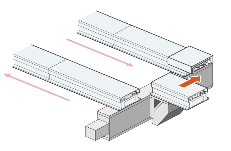
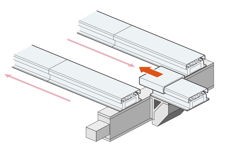
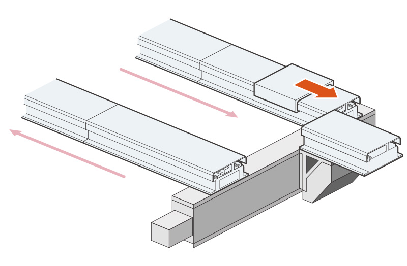
Point designation operation
Next movement point number for each slider is designated.
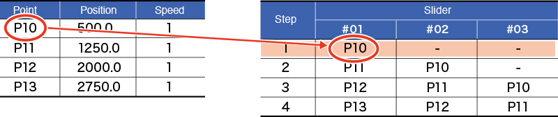
Point number is assigned to the slider.
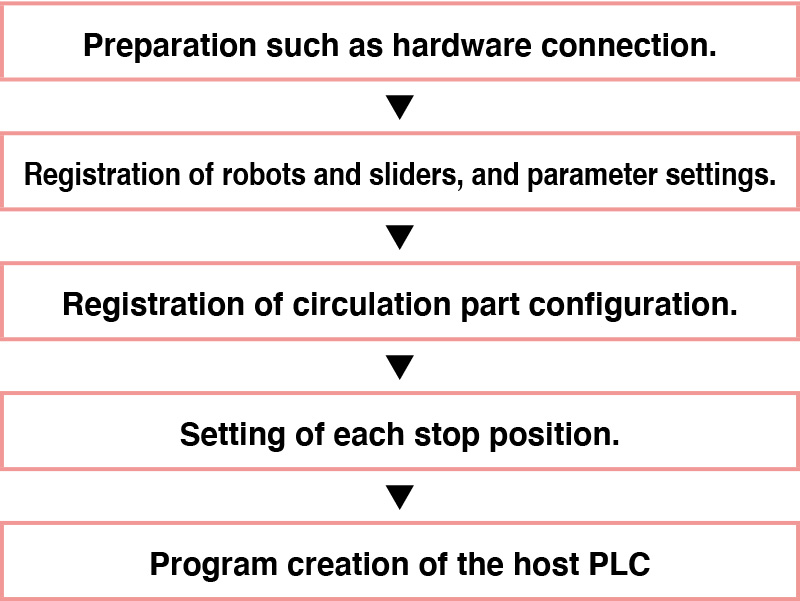
Process
Standard profile specification
| Applicable controller | YHX-HCU | |
|---|---|---|
| Operation method | Point trace point No. specified positioning and direct value coordinate specified positioning. | |
| Comparative robot | LCMR200, LCM-X and GX series (LCMR200 and LCM-X cannot be controlled together). |
|
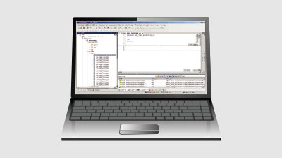
| Interface | YHX Studio, YHX-PP, and field network communication | |
| Operation type | Absolute position moving | |
| Maximum number of points that can be registered. | 65535 | |
| No. of control axes (Total of sliders and single-axis robots, however, up to 16 axes for single-axis robot) |
EtherCAT | 64 |
| EtherNet/IP™ | 64 | |
| PROFINET | 64 | |
| CC-Link | 22 | |
| Main input and output See the manual for other functions. |
All axes target input | Servo ON/OFF switch/Interlock/Alarm reset |
| All axes target output | Servo State/Interlock State/Alarm State/Heart beat/Emergency stop State | |
| Individual axis target input | Servo ON/OFF switch/Return to Origin/Positioning moving inside the control range (including LCM relay operation)/Slider insertion preparation from outside the control range/Slider discharge to outside the control range/Jog movement, inching movement/Movement Stop | |
| Individual axis target output | Servo State/Return to origin State/Output specified point No. for various execution state display/Current position/Axis alarm State | |
| Main remote command See the manual for other remote commands. |
Writing/reading of setting data | |
| Alarm check | ||
| Writing and reading of integrated running distance and No of transits. | ||

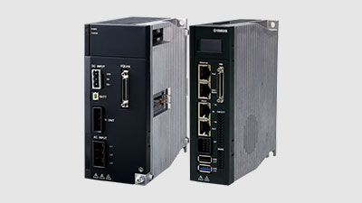
YHX Controller
Related contents
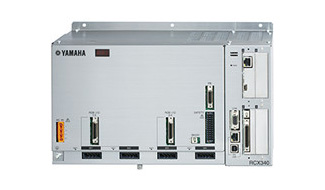
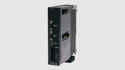
- Controller
- Introduces the robot controller with advanced functions. Select the ideal controller from various command input formats.
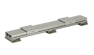
- Linear conveyor module LCM-X series
- Significantly improving the space occupancy rate, making better the transport accuracy and increasing the acceleration and deceleration performance, the linear conveyor modules realize higher level transport automatization ever before.
Robotics Operations
Sales & Marketing Section
FA Sales & Marketing Division
127 Toyooka, Chūō-ku, Hamamatsu, Shizuoka 433-8103, Japan
Telephone +81-53-525-8350 /
Facsimile +81-53-525-8378